Measurement of the temperature distribution at the tool-chip interface
This page has opened to public since 16 October 2015.
Measurement of the temperature distribution at the tool-chip interface
This page has opened to public since 16 October 2015.

 Japanese
|
All Rights Reserved by Dr. Shinozuka, Jun.
|
Temperature is one of very important physical parameter. As for machining process; Knowing cutting temperature is crucial for clarifying the cutting mechanism, optimizing the machining condition, and also, designing high-performance materials. Because dynamic material behavior depends on temperature. Moreover, tribological property, tool wear rate, surface integrity, and the performance of free-machining additives depend strongly on temperature.
In short, grasping cutting temperature is very important.
However, the cutting temperatures are not grasped practically. Because, The area of the tool-chip interface is too small. The interface cannot be observed directly. The high level of the stresses apply to the interface.
Measuring the temperature distribution at the tool-chip interface involves some difficulties. So, we have to know the cutting temperatures, especially, temperature distribution at the tool-chip interface. I have been trying to measure the temperature distribution at the tool-chip interface by employing various methods. Here, I would like to describe the previous works that I have done, briefly.
A Spot Temperature Measurement Method (1995)
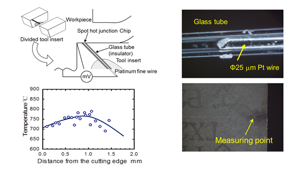
In this method, a Platinum wire with extra fine diameter is embedded in the tool, like this. The hot-junction is composed of the tip of the platinum wire and the chip surface. For this method, it is difficult to measure the temperatures at multiple points simultaneously.
Reference:
A Thin Film Thermocouple Method 1 ( average temperature measurement) (2004)
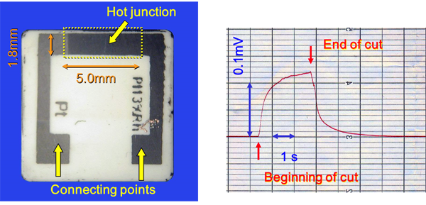
This is a method that thin film thermocouple is deposited on the rake face. The tool material is alumina ceramics, which is electrically insulated material. In this case, the average temperature over the tool-chip contact region can be measured.
Reference:
A Thin Film Thermocouple Method 2 (multipoint measurement) (2006)
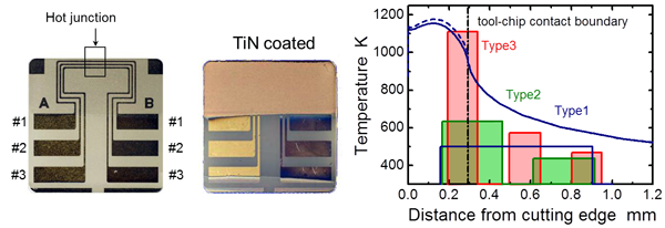
In order to achieve multiple measuring, I have developed the thin film thermocouple method, as shown here. The thin film thermocouples were fabricated on the rake face using lithography technique. The number of the thermocouples was three at maximum. By increasing the number of the thermocouples, the shape of the temperature distribution can be grasped gradually. But, the number of thermocouples was insufficient to grasp clearly the shape of the temperature distribution inside the tool-chip contact region.
Through the previous works, these points that should be improved are arisen. The number of thermocouples should be increased. The endurance of the thin film thermocouples fabricated on the tool face is relatively low, because they become obstacles against chip flow. Then, I have developed new tool with built-in micro thermocouples. In this tool, the micro thermocouples are set in the micro-grooves. And the number of measurement point is increased to seven in order to grasp temperature distribution more clearly.
Reference:
An indexable insert with seven pairs of built-in micro Cu/Ni thermocouples (2015)

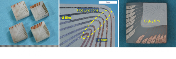
This is the new tool developed. In this tool, there are seven pairs of micro thermocouples on the rake face. Each element of the thermocouple is embedded in the micro-grooves. The hot-junction is formed in the plane normal to the rake face. The element of the micro thermocouple is Copper and Nickel. Both the element were fabricated in the micro groove with electroless plating and electro plating.
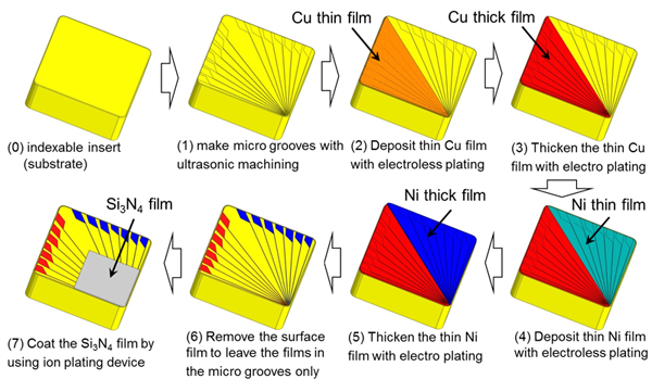
 Making process for the cutting tool with seven pairs of built-in micro Cu/Ni thermocouples
The making process for the tool is shown. The substrate is an indexable insert made of alumina ceramics. First, the micro-grooves are formed with ultrasonic machining. Then, copper film and nickel film are deposited on the surface with electroless plating and electro plating. After deposition, the extra film on the surface is removed with lapping. Finally, as an electrically insulated film, silicon nitride film is coated with ion plating.
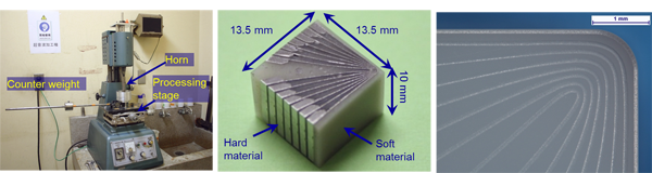
The micro-grooves are fabricated by employing A novel Ultrasonic Machining for Micro Grooving by means of a "Sandwich Tool". At the tip of the ultrasonic horn, this tool is attached. It is composed of hard material, which is stainless shim sheet, and a soft material. The shape of cross section of the hard material is the circuit pattern of the micro-thermocouples, as shown here. With this process, the micro-grooves can be fabricated as shown in the following photograph.
The material of the indexable insert as the substrate is an alumina ceramics. In order to increase adhesion strength, the alumina ceramics was etched with hot sodium hydroxide.

Copper film was deposited with electroless plating, first. Then the films were thickened with electro plating in order to fill the micro groove. The Nickel film was also deposited as the same way.
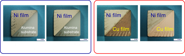
After plating, the extra film deposited on the tool face was removing with lapping process. Finally, as an electrically insulated film, silicon nitride film is coated with ion plating.
All of the process was carried out in my laboratory. In short, my students made it by their hands.
Calibration of temperature - emf property of micro Cu/Ni thermocouples
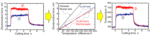
The property of the temperature and electromotive force was calibrated with this device developed. In this device, a focused halogen lump is able to heat the heating plate up to 1300 K under a vacuum condition. Through the calibration, it was found that the temperature and emf property of micro thermocouple fabricated with electroless plating and electroplating is the almost the same as the Cu/Ni wire thermocouple.

Example of the results of the temperature measurement experiment
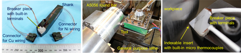
The cutting temperature measurement experiment was carried out with the indexable insert with built-in micro thermocouples developed. As shown in the photograph, in this method, the machine tool is used as it is. It is unnecessary to remodel a machine tool.
As shown in the following figure, this tool is able to measure the emf without any remarkable noises. The emf is converted to temperature like this, by use of the calibration result. 3 and 7 indicate the location of the hot-junction. The distance between number three and number seven is some 0.5 mm. In this small region, we can see that the temperature gradient over 100 K exists.
The results of the cutting temperature measurement experiment are shown below. The yellow region indicates the tool-chip contact region. We can see the shape of the temperature distribution at the tool-chip interface clearly, The difference of the temperature distribution according to the difference of the cutting speed can be grasped clearly.
For the future..., The indexable insert developed will be utilized for optimizing the cutting condition, improving the cutting performance and designing materials with high-machinability.

Reference:

